 Hydraulic Fracture 3-D Fracture Model – By Gopal Krishna Panigrahy")
Tip Screen-Out (TSO) Hydraulic Fracture 3-D Fracture Model – By Gopal Krishna Panigrahy
“Things looked grim for American energy in 2006. Oil production was in steep decline and natural gas was hard to find. The Iraq war threatened the nation’s already tenuous relations with the Middle East. China was rapidly industrializing and competing for resources. Major oil companies had just about given up on new discoveries on U.S soil, and a new energy crisis seemed likely.
By experimenting with hydraulic fracturing through extremely dense shale – a process known as fracking – the wildcatters started a revolution. In just a few years, they solved America’s dependence on imported energy, triggered a global environmental controversy – and made and lost astonishing fortunes.”
-The above is an excerpt from The Frackers, Gregory Zuckerman which is a book about how fracking changed the dynamics of the Oil industry.
Executive Summary
Tip Screen-Out and Frac-Pack are the non-conventional fracture treatments applied to high permeable oil and gas well stimulation. The application for either the TSO or Frac-Pack is more a function of the fracture efficiency than if it is of “hard” or “soft” rock. Lower fracture efficiencies (high reservoir permeability) favour the Frac-Pack while higher efficiencies (moderate permeability) favour the TSO methodology. Frac-pack not only increases flow conductivity but also acts as a sand control method in unconsolidated formation.
The TSO methodology is used to deliberately create a proppant screen-out or bridging condition around the perimeter of the fracture to prevent further fracture propagation and height growth. Continuous pumping results in “ballooning” or an increase in the fracture aperture while increasing the net fracture pressure. The increased aperture results in a greater propped width and increased fracture conductivity. Typically, only the perimeter of the fracture is packed.
Computer application auto design mode is the normal design practice due to inherent challenge in TSO fracture design. The numerical modelling techniques meet the requirement that the fracture propagation and proppant transport solution be linked in such a way that each can influence the other. This methodology differs substantially from a conventional fracture stimulation approach which by design tries to prevent proppant screen outs or bridging.
I.1 Introduction
Hydraulic fracture is a recognized well stimulation technology and widely used for production enhancement for both gas and oil wells. The success of the stimulation depends on careful candidate selection. Low permeability reservoirs are the primary candidates for fracture stimulation. Wells having high skin and excessive drop in pressure at near wellbore region are the other considerations. In the conventional hydraulic fracture operation, the well productivity is increased by creating a long and narrow fracture in the formation. The long and narrow fracture crosses the near wellbore damage and connects the natural fissures and increase the flow conductivity. During the hydraulic fracture operation, the transportation mechanism of solid proppants into the fracture tunnel is a key factor in increasing the flow conductivity and well productivity. Early proppant screen out could play a spoilsport in the frac job. Screen out is a condition that occurs when the solid proppant carried out in fracture treatment fluid creates a bridge across the perforations or similar restriction flow area. This results a sudden and significant restriction to fluid flow that causes a rapid rise in pump pressure.
However, the screen out if successfully applied at the fracture tip, the fracture geometry significantly changes. The fracture length and height growth are restricted, but width growth continues due to rise in fracture pressure. This short and fat fractures are possible in soft and relatively high permeable formation.
Hence the tip screen-out, also popularly known as TSO technology, quite contradictory to conventional frac method, are used for production enhancement in relatively high permeable soft formation.
I.1.1 TSO & Frac-Pack
Tip Screen-out (TSO) and Frac-Pack designs are generally performed in moderateto high-permeability reservoirs that require greater conductivity than achieved with conventional hydraulic fracturing. The implementation of TSO and Frac-Packs, over the past several years, has resulted in substantially greater fracture conductivities and improved proppant placement. As a consequence, these applications have gained popularity in the industry where inadequate conductivity and formation damage have been problems.
Frack-pack is achieved only after the Tip Screen-Out. Hence, TSO is invariably linked to Frac-pack and inadvertently not differentiated as a separate method. However classical TSO is not the same as Frac-pack which differs from TSO’s by packing the entire fracture with proppant from the tip to the wellbore at the settled bank concentration. The Frac-pack not only increases the flow conductivity but also acts as a sand control method due to greater control in the spatial distribution of proppant in the fracture. Typically, TSO’s are performed in moderate permeability “hard” rock formation whereas Frac-Packs have been successfully performed in high permeability unconsolidated “soft” rock formations. However, the present discussion is focussed only to classical TSO method and its design rather than the Frac-packs.
The TSO methodology is used to deliberately create a proppant screen-out or bridging condition around the perimeter of the fracture to prevent further propagation and height growth. Continuous pumping results in “ballooning” or an increase in the fracture aperture while increasing fracture pressure. The increased aperture results in a greater propped width and increased fracture conductivity. Typically, only the perimeter of the fracture is packed.
The key feature in high permeability fracturing is the tip screen-out (TSO) technique, which arrests lateral fracture growth and allows for subsequent fracture inflation and packing. The result is short but exceptionally wide fractures, an average fracture width of 1 in. or even larger.
 The TSO occurs when sufficient proppant has concentrated at the leading edge of the fracture to prevent further fracture extension. Once fracture growth has been arrested (and assuming the pump rate is larger than the rate of leak off to the formation), continued pumping will inflate the fracture (increase the fracture width). This TSO and fracture inflation should be accompanied by an increase in net fracture pressure. Thus, the treatment can be conceptualized in two distinct stage: fracture creation (equivalent to conventional design) and fracture inflation/packing (after tip screen-out).
In high permeability reservoirs, fracture stimulations require fluid system that leaks off early in a treatment. Dehydration of the slurry causes proppant to pack off at the fracture tip, halting further propagation, or extension. As additional slurry is pumped, bi-wing fractures inflate and proppant packs toward the wellbore. A TSO treatment ensures wider fracture and improves conductivity by promoting grain-to-grain contact in the propant pack.
I.2 Methodology
The design of a TSO frac stimulation is a bit challenging, hence computer applications in auto design mode is adopted. Numerical simulation methodologies are used to design TSO type proppant distributions. The modelling techniques require that the fracture propagation and proppant transport solution be linked in such a way that each can influence the other. Normally, this means that for each time step in the fracture propagation calculation, the proppant transport simulation must be assessed and coupled. This methodology differs substantially from a conventional fracture stimulation approach which by design tries to prevent proppant screen outs or bridging.
For a TSO design the slurry treatment must be scheduled such that as the earlier stages concentrate, due to slurry dehydration or leak-off, the later stages fill the void created by a continuous and declining rate of fluid loss. For a typical TSO job, a pump schedule is important to create the specified fracture properties; a pump schedule can be designed using analytical formulae based only on fluid efficiency. The slurry schedule is planned so that only low-concentration slurry is near the fracture tip during pumping; this is achieved by pumping an extended low concentration stage, normally 1 PPG before the slurry concentration is increased. The front of this low-concentration stage initiates screen out, and the first part of the higher-concentration slurry stage should reach the fracture tip at the end of pumping. The logic that this approach should minimize the aperture increase for a given pressure rise. When modelling TSO, the first requirement is to estimate the desired fracture length and height needed at the start of the TSO; this step have to be done according to the geological conditions, well pattern, well spacing and well density using 3D reservoir simulation model. Secondly, fracture simulation models will be used to estimate the time required to reach a TSO and fluid efficiency at TSO need; the pad volume, the time to start the low concentration proppant stage, the time to end the of the main slurry stage, the time to start the mean slurry stage and the proppant concentration for the given volume time need to be calculated according to the selected model.
Computer applications are specifically developed to automatically design a TSO and output the corresponding treatment schedule. Therefore, the following discussion is directed toward using the Auto Design capabilities for TSO.
The user specified criteria (e.g., target Frac Length, Initial and Max. Inlet Concentration, Average Concentration/Area and Max. BHP), the program is allowed automatically design a pumping schedule that optimizes a tip screen-out condition (TSO). Once a screen-out occurs, the net pressure will continue rising during the remaining part of the treatment to meet the desired design criteria. During this type of simulation, the linked solution methodology permits continuous proppant transport calculations as the slurry is concentrating in the fracture due to leak-off.
The program always satisfies the specified length and then, if possible, the average concentration per unit area. User specified constraints are used as absolute limits and maintain the following priority: Maximum BHP has first priority, Max. Proppant Concentration (lbm/ft2) in the fracture is second and Maximum Inlet concentration is last. If any of the specified criteria are not met, it means that a higher priority constraint was imposed.
The result is a proppant distribution that approaches a uniform concentration per unit volume throughout the fracture based on the target concentration per unit area specified.
I.2.1 Design Criteria
The criteria for automatic TSO designs include:
i. Designing to a pre-specified fracture length to optimized near wellbore conductivity;
ii. Basing the design on a maximum allowable inlet concentration;
iii. Designing to achieve a minimum concentration per unit area; and
iv. Maintaining pumping pressures below a critical maximum
I.2.2 Procedures
In terms of procedures, operations should design for a target fracture length. After aperimeter tip screen-out is achieved, fracture extension (length and height growth)will stop and the fracture width and pressure will begin to increase. The rate of fluid leak-off begins to decrease.
For a TSO, the fracture pressure is allowed to continue increasing until the minimum concentration per unit area is satisfied or the pressure rises to the maximum allowable value. The TSO methodology assumes a constant injection rate duringthe entire pumping schedule.
Because excess ballooning is permitted in a TSO, the inlet concentrations to approach a “fully” packed fracture akin to Frac-pack are not feasible.
The behaviour of the fracture length (extension) is similar to Frac-pack, but inlet proppant concentration for a TSO increases continually with time (after the initial TSO stage) until it reaches a maximum pre-specified inlet concentration.
If leak-off is a strong function of fracture pressure, the leak-off coefficient would change more drastically for a TSO than a Frac-Pack because of the continued increasing net fracture pressure with time after a TSO.
The fracture net pressure and width both increase with time after a TSO.
As mentioned earlier, TSO’s are typically performed in moderate permeability “hard” rock formation whereas Frac-Packs have been successfully performed in high permeability unconsolidated “soft” rock formations. The propped width for a TSO (no settling) will be equal to the ratio of the slurry concentration in the fracture at the end of pumping divided by the settled bank slurry concentration. If 20/40 Jordan sand is placed at a maximum proppant concentration of 12 lbm/gal (7.8 lbm/gal slurry) theTSO propped width ratio would be 0.61 (i.e., bank concentration of 30.5 lbm/gal liq(12.8 lbm/gal slurry). This clearly illustrates why many TSOs are ballooned to a much greater extent than necessary to achieve the same concentration per unit area as a Frac-Pack.
For a typical TSO job, a pump schedule is important to create the specified fracture properties; pump schedule can be designed using the analytical formula based only on fluid efficiency. Fracture efficiencies (typically less than forty percent). The lower the efficiency the easier and quicker it is to achieve a TSO.
Other important considerations are the minimum allowable flow rate, proppant settling, time/pressure dependent leak-off, spurt loss and changing fracture compliance. The numerical procedure developed here for 3-D (and 2-D) TSO’s automatically accounts for these effects and other time dependent parameters generally ignored in analytical solutions.
Some of the key TSO characteristics are highlighted below:
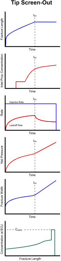
Fracture length increases as a function of time up to the point of screen out. After a perimeter screen out is achieved the propagation of the fracture stops and the width increases as a function of net pressure.
The minimum and maximum proppant concentration are user-specified constraints. Based on these values, the target length and average concentration per unit area specified to produce a pumping schedule that meets the criteria specified.
For a Tip Screen-Out design, the fracture area approaches a state of equilibrium once a screen out occurs. Beyond this point, the rate of leakoff declines. For a TSO design the program allows the pressure to increase by maintaining a constant rate of injection (i.e. balooning).
The time at which screen-out occurs is charcterized by a prominent rise in pressure. For a TSO treatment, the increase in pressure continues till the end of job.
After a perimeter screen out is achieved the propagation of the fracture stops and the width increases as a function of net pressure.
Because, ballooning is permitted in a TSO design, the inlet concentration required to pack a fracture are typically not feasible. For these type of traetments the stages pumped early in a job concentrate near the front of the fracture and results in higher concentration at the tip.
I.3 Numerical Simulation
This methodology is applicable for all types of 2-D and 3-D type fracture geometry models. It is a simple methodology based on sound engineering principles of mass and momentum conservation. Since this methodology has been incorporated in a numerical simulator, implementation of different boundary conditions or assumptions is possible and the effect of such changes quantified. Although all the underlying boundary conditions outlined in this methodology may not always be satisfied, these tools enable the design engineer to investigate the simplicity of this first order analysis and how substantially it deviates from conventional fracturing.
To illustrate the TSO methodology an automatic design was numerically simulated based on the following criteria on a vertical light oil well of a single sandstone pay zone, named Zone-A at a perforation depth interval of 12000 to 12660 ft.
i. Pre-specified fracture length of 500 feet;
ii. Maximum allowable inlet concentration of 10lbm/gal liquid;
iii. Designed to achieve a concentration per unit area of 2lbm/ft2; and
iv. Maintain a pumping pressure below 10,000 psi.
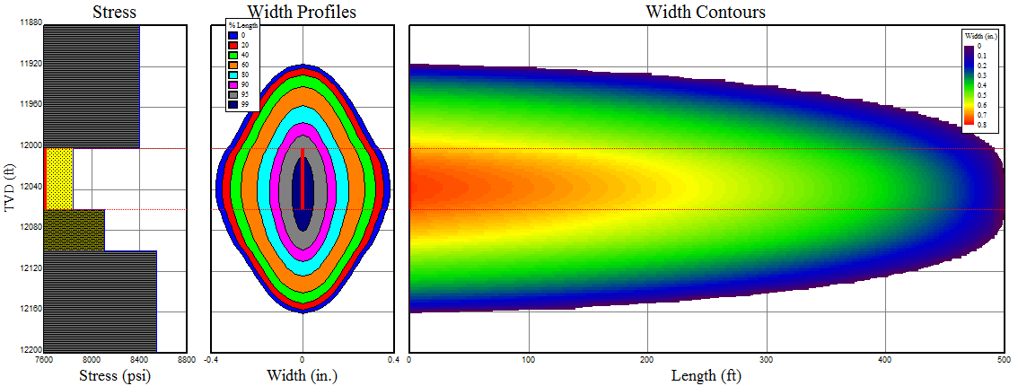
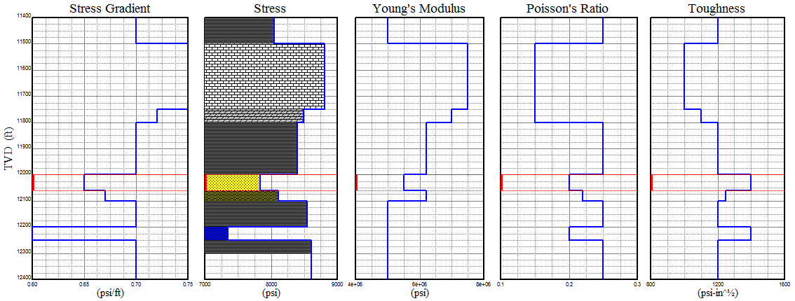
Formation Rock properties are shown in the table and graphical form below:
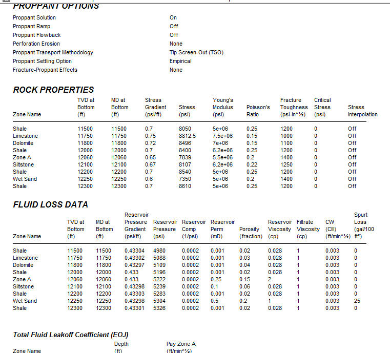
A treatment schedule was prepared by considering an injection slurry rate of 35 bpm for a viscous watery fluid and 20/40 Jordan sand as proppant.
Fluid leak off characteristics and the pumping pressure are shown below. The calculation honours the maximum specified pumping pressure limit 10,000 psi.
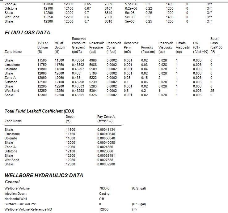
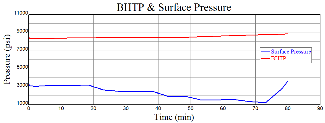
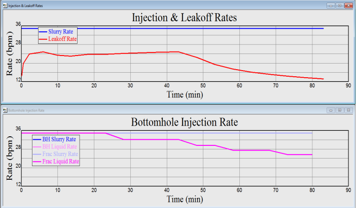
Figure below shows the inlet slurry, liquid and resulting leak-off rate as a function of time which satisfy the pre-specified TSO criteria. A constant slurry rate of 35 bpm was pumped throughout the stimulation job. The leak-off rate drops drastically after the tip screen-out which happened at 43 minutes. Also, the liquid rate decreases and causes increase in inlet sand concentration. Constant slurry rate and drop in liquid injection rate is the reason for the ballooning of the fracture.
Figures below illustrate the simulated automated inlet proppant concentration schedule. The job is started with a low concentration of 2 ppg and gradually increased to 8 ppg after achieving TSO.
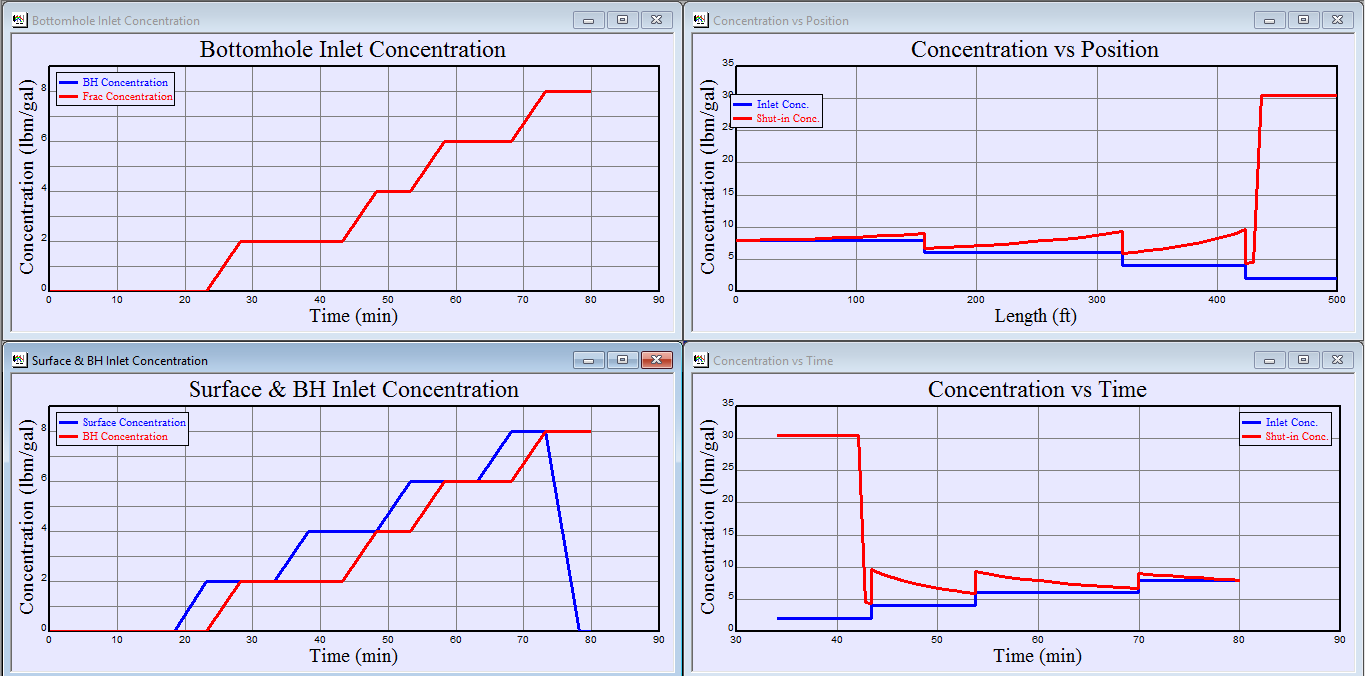
Concentration per unit area never crossed the upper limit of 2lbm/ft2. Mat the end of the job and in closure, it maintained the limit. At the closure, a proppant distribution approached a uniform concentration per unit volume 55 ppg throughout the fracture based on the target concentration per unit area 2lbm/ft2 specified.
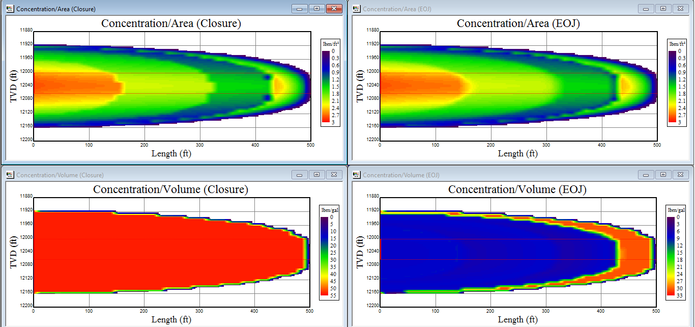
Once the design fracture length is achieved at about 43 minutes, fracture extension (length and height) stopped as a result of the tip screen-out condition. The fracture continued to balloon from 43 to 80 minutes to a width of about 0.7 in. to meet the maximum design concentration/area of 2lbm/ft2.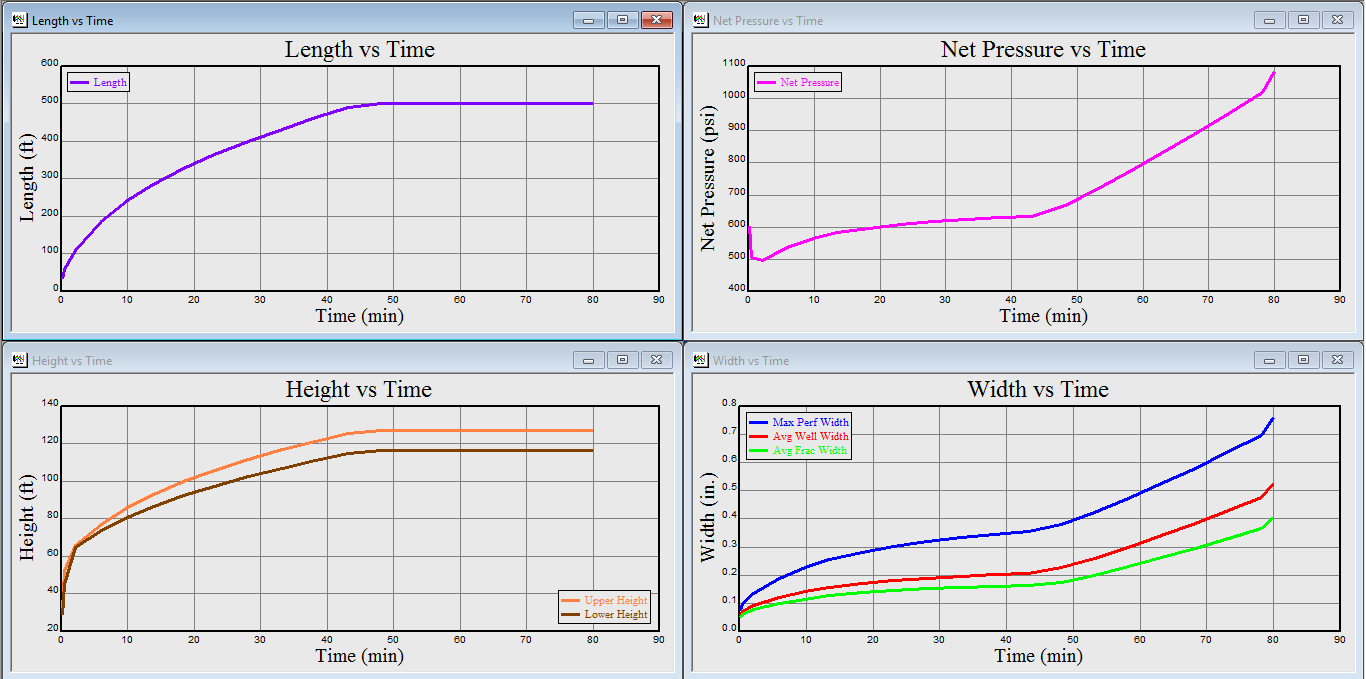
Figure below shows the behaviour of fracture efficiency as a function of time. The TSO frac are invariably low frac efficiency due to high leak-off rate and remained below 40%. After the fracture propagation, rate diminishes at 43 minutes and the efficiency rises as a result of the decreased leak-off rate. The fracture efficiency at closure represents the fraction of propped volume to total injected slurry volume.
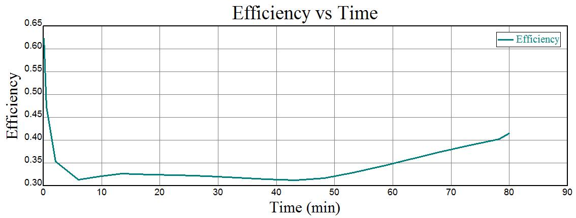
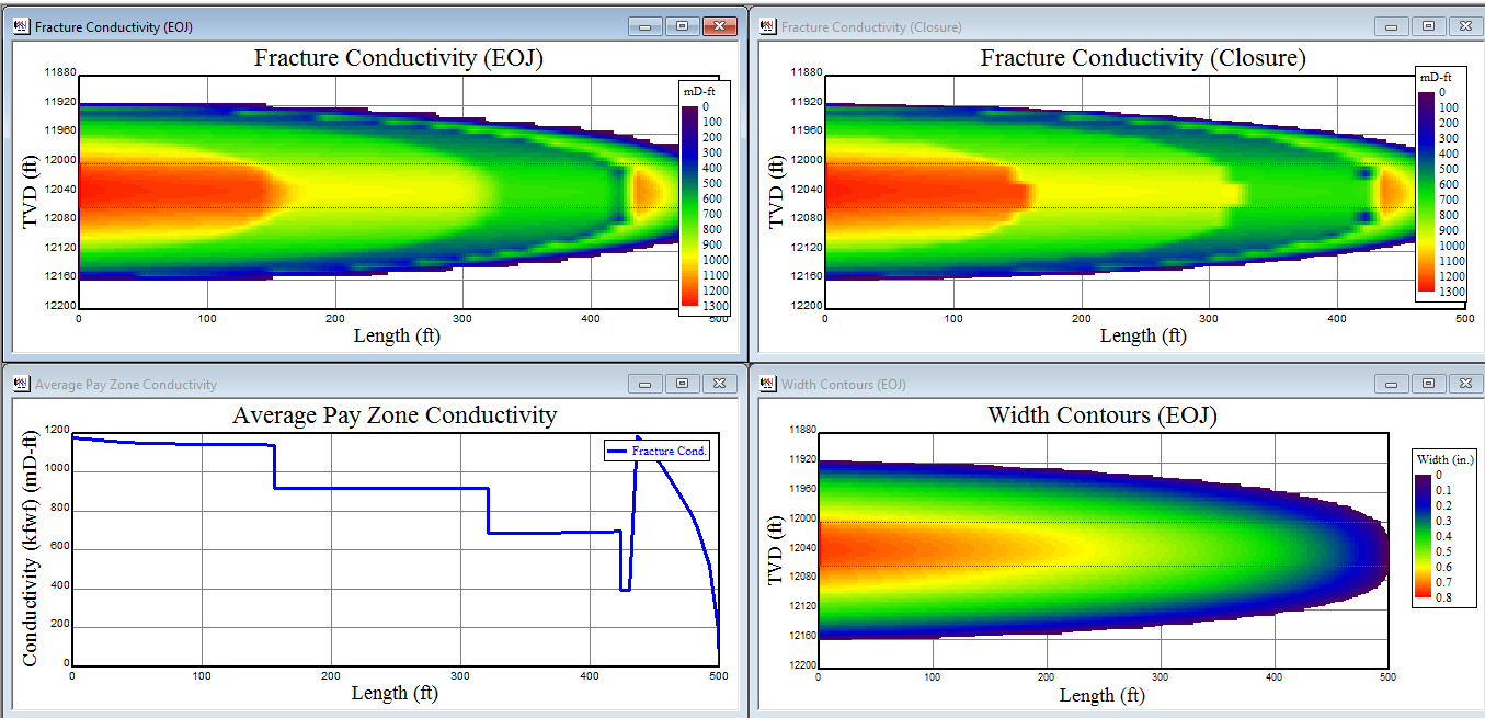
Figure below shows the increase in conductivity due to increase in width. The conductivity near wellbore is higher and gradually reduces along the fracture length.
The above figures illustrate the TSO methodology as implemented in 3-D hydraulic fracturing simulator. The advantage of using a numerical simulator is that the leak-off rate, compliance factors, spurt loss, height growth and other typical simplifying analytical assumptions made by 2-D models are not necessary to solve the governing equations.
Author – Gopal Krishna Panigrahy, Head Operations, North East, HOEC. To know more about the author please goto https://hoec.com/team/gopal-panigrahy/ to find an interview with him.
References:
1. Smith, M. B., Miller, W.K. and Haga, J.: “Tip Screenout Fracturing: A Technique for Soft Unstable Formations,” SPEPE, May 1987, 95-103.
2. Martins, J.P. and Stewart, D.R.: “Tip Screenout Fracturing Applied to the Ravenspurn South Gas Field Development,” SPE Prod. Eng., Aug. 1992, 252-258.
3. Fan, Y. and Economides, M.J.: “Fracture Dimensions in Frac&Pack Stimulation,” Paper SPE 30469 Presented at the 1995 Annual Technical Conference and Exhibition, Dallas, TX, Oct. 22-25, 1995
4. FracPro Hydraulic Fracture simulator
5. MFRAC Hydraulic Fracture simulator
6. STIMPLAN Hydraulic Fracture simulator